
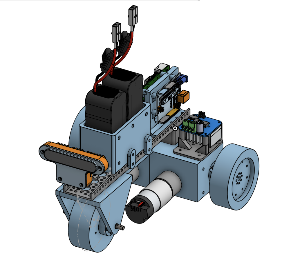
Monkeybot
Team Inspiration created MonkeyBot, a specially designed educational robotics platform that teaches end-to-end robotic system design and control. It combines an Arduino and a Raspberry Pi, with the Arduino handling low-level motor control and the Raspberry Pi running Python code to handle high-level logic, computer vision, and sensor processing. In addition to supporting controller-based manual operation, MonkeyBot can convert visual input into real-time steering decisions using a camera and vision algorithms like HSV color identification and object tracking. MonkeyBot is a solid foundation for more complex robotics projects like RoboBoat because it gives students practical experience with robotics fundamentals like system integration, feedback, autonomy, and problem-solving through assembly, wiring, configuring Wi-Fi and SSH access, and debugging both hardware and software.
What is MonkeyBot?
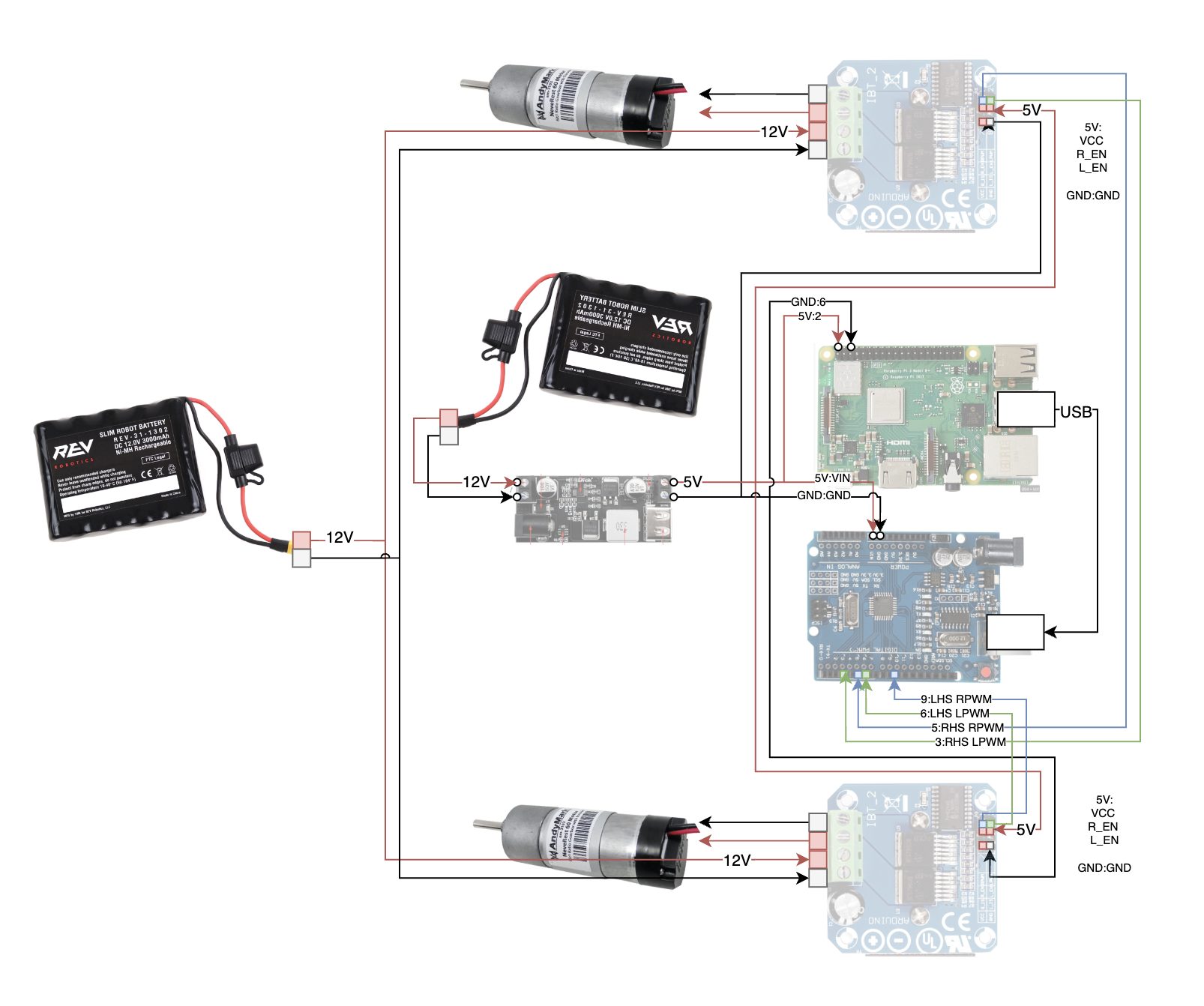
1) Power distribution (12 V → 5 V):
A 12 V battery is the main power source. It feeds the motor drivers directly (because DC motors need higher voltage).
2) Motor control path:
Each DC motor connects to an H-bridge motor driver.
Control pins (R_EN, L_EN / direction + PWM) come from the Arduino.
3) Arduino (real-time control):
The Arduino outputs PWM signals to the motor drivers.
PWM controls motor speed; direction pins determine forward/reverse(-255, 255)
The Arduino is powered by the shared 5 V rail and ground.
4) Raspberry Pi (high-level logic):
The Raspberry Pi also runs on 5 V from the buck converter.
It handles higher-level tasks (vision, decision-making, controller input).
The Pi communicates with the Arduino (typically via USB or serial) to send movement commands, not raw motor signals.