
RobotX - Sub Sensors
RobotX 2026 > Sensors
Inertial Measurement Unit (IMU)
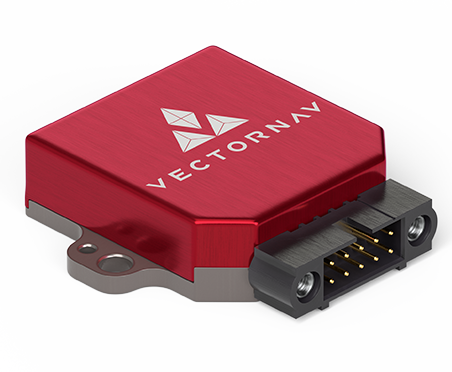
To navigate and localize around the mission course, we need the 3-axis heading and acceleration data, which we can use to determine the subs’ position. The Inertial Measurement Unit (IMU) is the sensor that allows us to achieve and obtain these variables. We integrated our Vectornav VN-100 IMU into Graey for greater precision and accuracy in heading and rotational acceleration data. In the previous competition, our UUVs were significantly impacted by electromagnetic interference (EMI) from the pool structure. IMU’s automatic Hard and Soft Iron (HSI) calibration feature mitigates magnetic interference from electromagnetic and metallic sources.
Doppler Velocity Log (DVL)
To localize Graey, we use a Doppler Velocity LOG (DVL) to process position estimation from obtaining their velocity input. The DVL estimates velocity relative to the sea bottom by sending acoustic waves from the four angled transducers and then measures the frequency shift (the Doppler effect) from the received echo. By combining the measurements of all four transducers and the time between each acoustic pulse, it accurately estimates the speed and direction of movement.
Graey uses an A50 DVL from Water Linked, which gives us reliable navigation data for accurate waypoint following and position holding. The team also explored manufacturing feasibility and ran simulation analyses to reduce risk and verify our design assumptions.
Imaging Scanning Sonar
We switched to Ping Sonar from Blue Robotics for its increased image scanning capability. Previously, we used the one-dimensional ping sonar, which only allowed us to receive distance values in the direction the sonar was pointing. The new 360-degree sonar allows us to get a snapshot view of our whole environment so we can analyze where the mission objects are and which direction we should head in.
Barometer
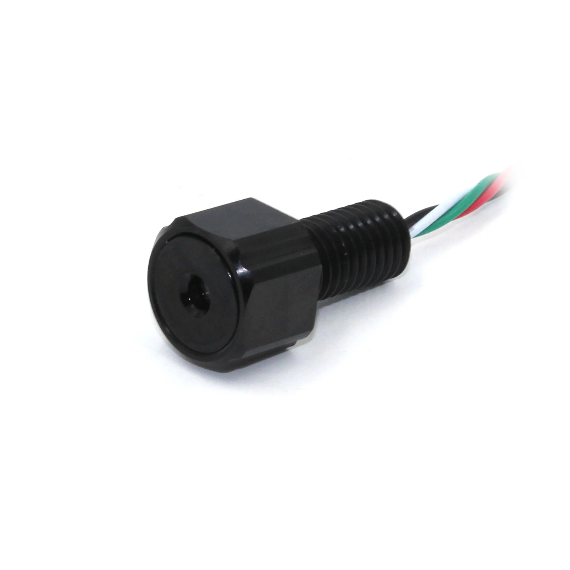
In the 3-D environment of the water, we introduce the axis of depth, the z-axis. The mission course requires us to have the capability to sense and adequately adjust our depth to move under, move above, and align with the task elements. The barometer is the sensor that allows us to obtain the measurement, which is aligned with the flight controller, so that we can directly hold or set our depth. We developed our own Proportional Integral Derivative (PID) controller, which reads pressure from a barometer, to implement depth hold capabilities
Cameras
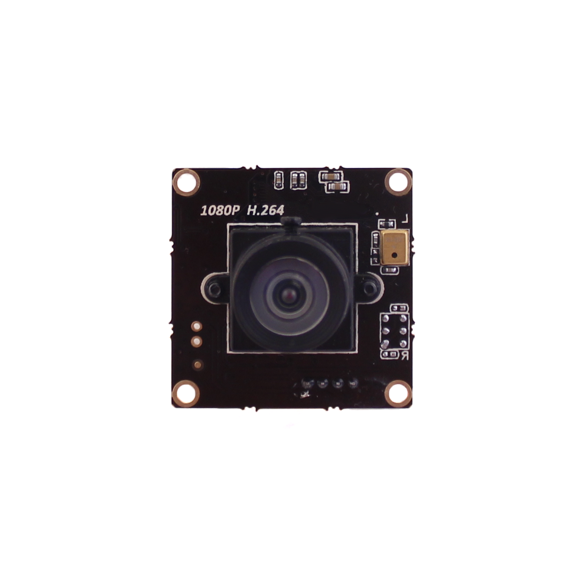
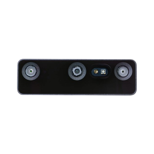
As of now, Græy is equipped with a forward-facing OAK-D Wide and a bottom-facing USB low-light. OAK-D cameras divert processing power from our onboard computers, allowing us to easily run YOLOv8 models for object detection. We switch to USB low-light cameras when using OpenCV color thresholding and other OpenCV methods as they allow for higher resolution images in low-light conditions.
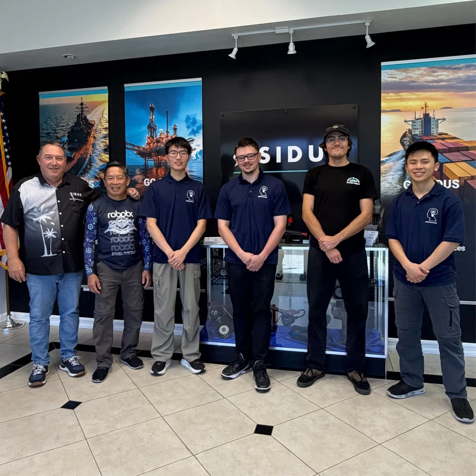
We are planning to replace the bottom-facing USB low-light camera with the Sidus Camera. Upon integration, we modeled the Sidus camera's field of view and proposed a placement for it.
Modem
To safely and effectively operate our boat and sub simultaneously in the water, it is paramount to have a consistent and efficient communication system. This season, we emphasize the importance of being able to have two vehicles effectively communicate with each other in the water, in addition to providing useful information to the ground station, such as images, updates on current tasks, and other odometry status messages. Our original design was modeled around the compact m64 modems by WaterLinked. To test these modems, we developed a bench test utilizing a Raspberry Pi and a hobbyist power divider/regulator for power and serial communication. The results of these modem tests demonstrated that they were unreliable and their 64 bits per second were insufficient if we desired to send any images. This led us to begin implementing new modems (Succorfish Delphis modems)that were more reliable and offered a higher bandwidth.
Hydrophone
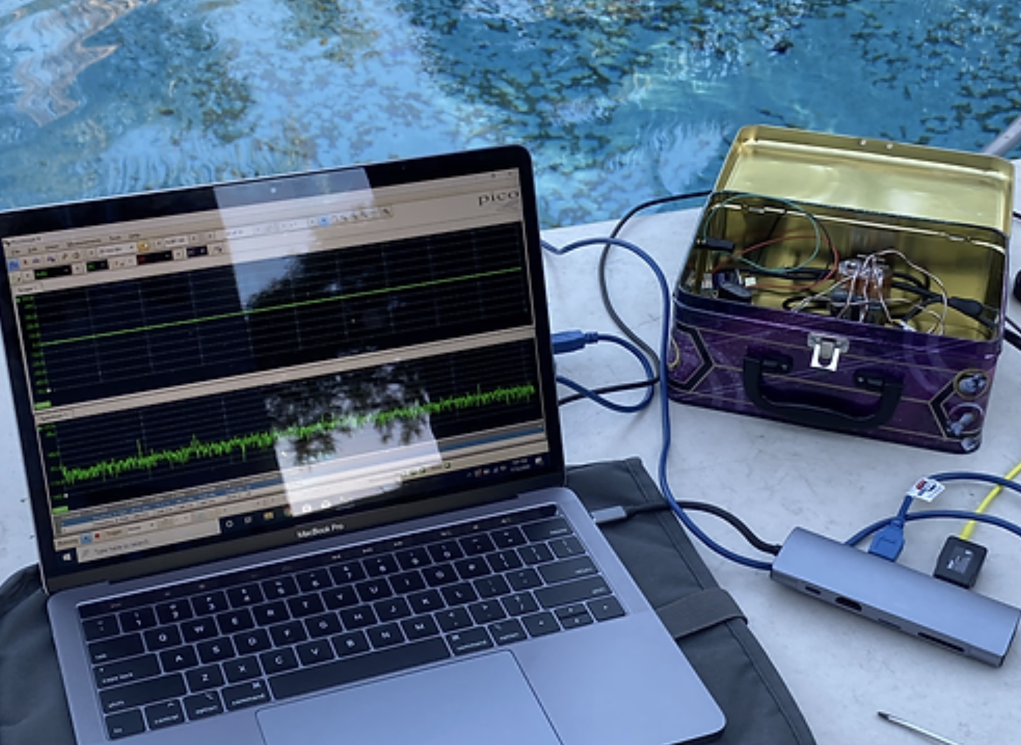
We offloaded as much filtering as possible to custom-designed hardware, freeing up resources within the microprocessor. Each hydrophone has its own daughterboard containing noise-isolated circuitry. This includes the pre-amp, a custom amp, a custom variable frequency filter, adjustable between 10khz to 40khz, a digital potentiometer for variable gain, and a custom active high-pass filter to ensure the signal is as clean as possible.